Saturday, August 13, 2011

Mechanical Hangar (Autobot Hangar) Part 4

More painting and detail updates....

1. Masked the floor to paint caution area.


2. Painted some plastic tubes to be added as the tanks and fuel holder for the hangar.


3. Here are some more updated photos. Detail update includes:
a. Painted plastic tubes installed to the back wall.
b. Weapon holder (made from Chain base parts) installed to the side wall.
c. Dribrushed scaffolding.
d. Installed hangar lift to side wall.
e. Installed utility power lines to back and side walls.


4. Let's end with few diorama shots (Optimus Prime was intruducted to this battle axe and gatling gun).


Thanks for reading~

Tuesday, August 9, 2011

Mechanical Hangar (Autobot Hangar) Part 3

A quick update on Autobot Hangar..... (mainly painting hangar floor)

1. Added some more details. Namely added straws to be served as utility pipings.

2. Applied surfacer.

3. Small amount of Mr. Color Black on the edges of panel lines to create shadow and gradient effects later.


4. First coat using Mr. Color Steel.


5. Close up after second coat.


6. After some detail painting, washing, and sponging.


7. On to the side and back wall!


Thanks for reading~ More to follow.


Zebu

Monday, August 8, 2011

Mechanical Hangar (Autobot Hangar) Part 2

Howdy!,

Here is quick update.

1. Soldered single LED and secured on to the Mechanical Chain #4 light fixture using epoxy.


2. Here are four work lights which, will luminate the hangar from the front/side. As you can see, they are quite exposed looking.


3. Next, using 2mm styrene strip, I've made protative guards and secured it using super glue. Here is finisned look after coloring it black.


4. A shot of hangar afer side/front work lights are installed.


5. Added more railing to the ceiling.


6. All lights are installed (total 20 bright white LEDs so far).


7. Final few shots. More to come! Thanks for reading.

-Zebu-


Sunday, August 7, 2011

Mechanical Hangar (Autobot Hangar) Part 1

Howdy!

I’ve always wanted to make mechanical hangar for my models and kits. The purpose of this hangar would be used as a background for photo shoot as well as the quick diorama base (i.e. repairing or maintenance scene).

Finally, watching the movie "Transformer: Dark of the Moon" inspired me to get on with it.


Logistics

1. Kotobukiya Model Support Goods (MSG) Mechanical Chain Base #4 x 4
http://www.hlj.com/product/KBYMB-13
2. Kotobukiya Model Support Goods (MSG) Mechanical Chain Base #9 x 4
http://www.hlj.com/product/KBYMB-18
3. Epoxy
4. LED Flash light (I used the one can came with 21 LEDs).
5. N scale straight pier girders (Local model train store).
6. Computer IC sockets (old cell phone or used ‘and broken’ computers).
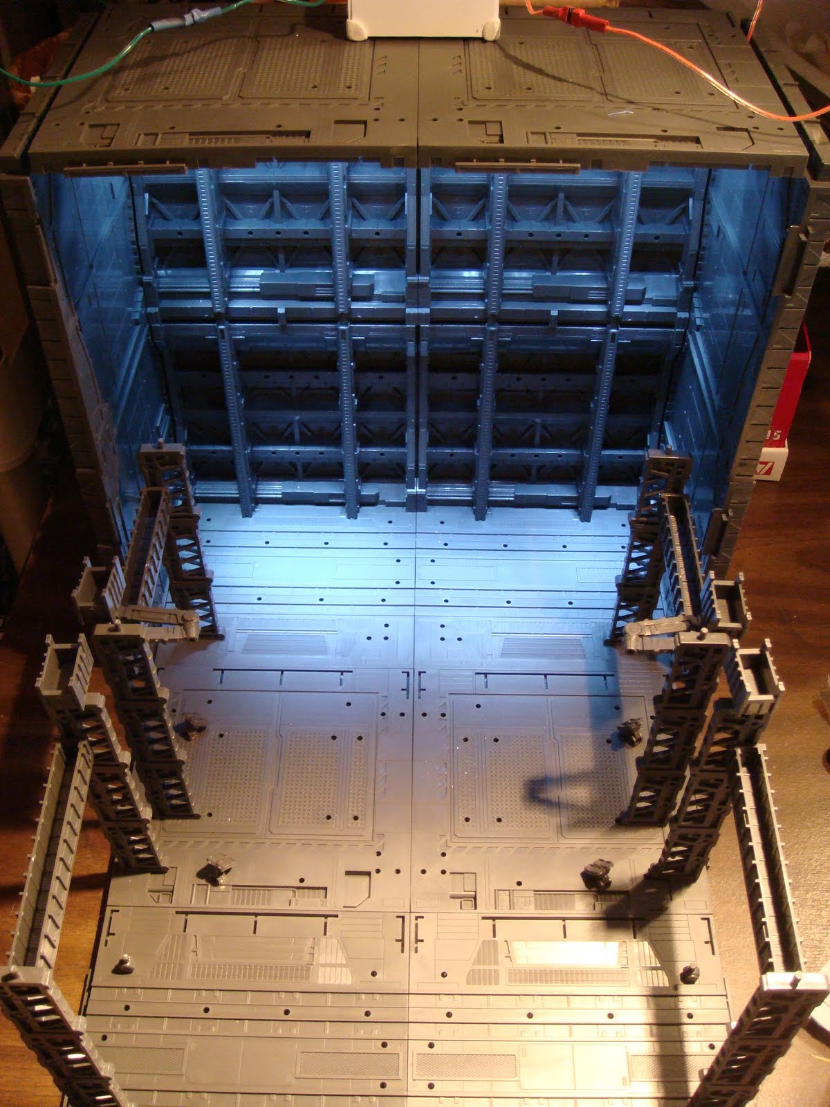
Procedures

1. I used 4 mechanical chain base #9 to form the back wall and 4 mechanical chain base #4 to form the sides (two on each side).

2. Next, I took apart the LED flash light (*quick background story… I bought this LED flash light from a local yard sale. It was suppose to be water proof; owever, the O-rings were broken and it was no longer functional. I saw it as potentially usable 21 LEDs for less than $2. Not only LEDs were fine, I was able to reuse the battery compartment, and switch. Normally, 21 bright LEDs, battery compartment and the switch can be expensive.... Lesson learned folks: Don’t always buy “new stuff that are specifically designed for model kits” take a look around and there are plenty of reusable things for your models). I took out all LED lights from its circuit and cut them in sets of 3, 2, and 1. It is important to save the circuit board because it will save your work to having to solder them again later.


3. Next, I soldered the wires on to the LEDs and arranged/scured them using epoxy as shown below. I’ve used four, 3 set LEDs on the back row and just two, 2 set LEDs on the front row to create the back-light effect.


4. Next, I built a battery holder to fit my flash light battery compartment using some plastic sheets. I’ve attached old IC sockets at the end of the wires to be served as the plug for easy battery and switch installations.


5. Test shots after the initial installation. I found it bit cheesy looking to see the LEDs directly exposed..... so on to the next steps.


6. Next, I used N scale straight pier girders to decorate the top (In front of the LED lights). These will be used to hang maintenance equipments and etc.


7. Here are the results so far.


More to come folks~ Thanks for reading.


Zebu